ENROL WITH UFMFLN-15-3 SATELLITE COMMUNICATIONS ASSIGNMENT HELP AND HOMEWORK WRITING SERVICES OF EXPERTSMINDS.COM AND GET BETTER RESULTS IN UFMFLN-15-3 SATELLITE COMMUNICATIONS ASSIGNMENTS!
UFMFLN-15-3 Satellite Communications Assignment - University of the West of England, UK
Learning Outcomes -
1. Apply concepts of satellite communication systems associated with the operation of satellite communications networks.
2. Demonstrate the use of advanced knowledge to solve basic and advance radio link design problems associated with satellite communication systems.
3. Apply skills required to design an end-to-end satellite communications link budget, based on standard engineering practices.
4. Identify the commercial, economic and social context of communication engineering applications that are affected by satellite communication systems.
5. Demonstrate the independent learning ability required for continuing professional development.
Task - Designing and Simulating a Geo-Stationery orbit Satellite Communications Link for a Lossy Communication Channel. Design and simulate an end-to-end Geo-Stationery orbit satellite communications link over a lossy satellite communication channel using MATLAB simulation software. The primary function of the satellite link is for data communications in Oman.
The primary losses involved in the channel will be:
i) Free space loss
ii) Atmospheric attenuation (Sandstroms and rain)
iii) Depointing losses
iv) Polarization mismatch losses.
Answer -
1. ABSTRACT:
This paper describes the details of satellite communication system. In the first part, it describes its application, advantages and disadvantages. Then it explains the structure of RF satellite link and RF Noise modeling. Orbital mechanics is mentioned with details and calculations.
2. a. HOW A SATELLITE WORKS
Satellite isused in Broadcasting, TV's and radio tuning, Web based applications, voice interchanges, innovative work segment, in numerous zones, military applications and routes, Remote detecting applications and Weather condition observing and Forecasting.
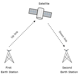
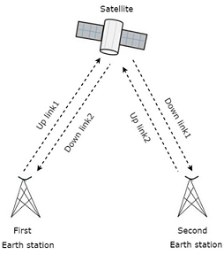
The whole process starts with the earth surface, whereby the signals are procured from the satellite to the two stations present over the earth surface, thereafter, the data is transmitted back to the satellite known as recurrence signals, measured in GHz. Then the signal passes by the repeater circuit to improve the quality. Thus the signal's recurrence band get alters. The passed on signal to the space is known as Uplink and opposite to this is known as Downlink and following figure shows this arrangement.
24/7 AVAILABILITY OF TRUSTED UFMFLN-15-3 SATELLITE COMMUNICATIONS ASSIGNMENT WRITERS! ORDER ASSIGNMENTS FOR BETTER RESULTS!
b. SATELLITE COMMUNICATION AT-A-GLANCE
|
Sl. No.
|
Advantages
|
Disadvantages
|
|
1
|
Transmission cost is free of inclusion territory
|
Backing up of the frequencies
|
|
2
|
More transfer speed and flexibility
|
Interference and engendering
|
|
3
|
Broadcasting conceivable outcomes
|
Free space misfortune is more
|
|
4
|
User friendly
|
The starting costs, for example, the cost associated with portion and dispatch are very high.
|
|
5
|
Ease in putting in new circuits
|
Very difficult to fix any dispute in a satellite framework
|
3. SYSTEM ARCHITECTURE
To model any communication building, some blocks are required:
(i) Path loss (free space)
(ii) Noise at receiver end (thermal) and phase
(iii) Droppler error
(iv) Offsets (DC level)
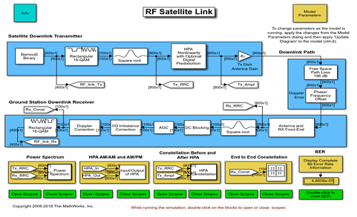
Satellite Downlink Transmitter
It applies gain to the transmitter section and transfer to receiver section which is also a data.
The thermal_noise is the cause of noise block at the receiver end.
The block which helps to select the phase and frequency offset in terms of error, is known as Droppler error. There are options like 0Hz and by adding 3MHz with given carrier frequency.
There are 3 options in phase noise like negligible (-100 dBc / Hz), low (-55dBc / Hz) and high (-48 dBc / Hz). The low and high noises are visible in both spectral and I/Q domains
There are some correction blocks like DC offset correction, Droppler correction, and I/Q imbalanced correction.
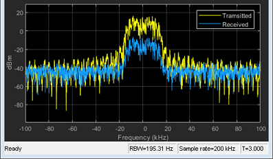
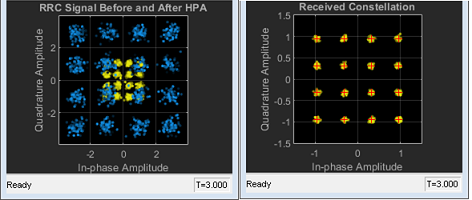
For this block diagram it gives output of power spectrum. There is a option for comparing output with 16 QAM.
GET ASSURED A++ GRADE IN EACH UFMFLN-15-3 SATELLITE COMMUNICATIONS ASSIGNMENT ORDER - ORDER FOR ORIGINALLY WRITTEN SOLUTIONS!
SYSTEM ARCHITECTURE
The RF system consists of:
(i) RF block to omit unwanted noise signal.
(ii) The details of external Noise source are temperature =2 K, impedance= 2 and noise phase = - 174 dBm/Hz.
(iii) The amplifier eases noise and ultimate power.
(iv) Output voltage is sensed by Voltage Sensor.
(v) Some required resistors.
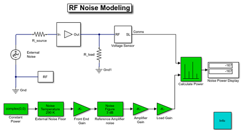
The Green region is the Communications Toolbox, consists of:
(i) The amplifier gain obstructs intensifier and stacking impacts.
(ii) Thermal Noise obstructs enhancer commotion as well as outer clamor.
(iii) Load =2 and resistance = 1 Ohm.
Steps for callback work:
(i) Under Configuration block dialog Choose Simulate noise.
(ii) Stipulate the Temperature and Noise figure (dB) for all amplifiers.
(iii) Then calculate the noise power at output.
(iv) Communications Toolbox Amplifier Gain block's output = RF Block-set R_load block's voltage.
4. ORBITAL MECHANICS OF SATELLITE COMMUNICATION -
The satellites are rotating around the earth in a circular path. The available movement analysis of the satellites in circles is known as Orbital mechanics. Orbital components are necessary for portraying satellites' orbital movement. The components are:
(a) Semi real pivot,
(b) Mean oddity,
(c) Inclination,
(d) Eccentricity
(e) Argument of perigee,
(f) Right climb of rising hub.
NO PLAGIARISM POLICY - ORDER NEW UFMFLN-15-3 SATELLITE COMMUNICATIONS ASSIGNMENT & GET WELL WRITTEN SOLUTIONS DOCUMENTS WITH FREE TURNTIN REPORT!
The nearest point of a satellite from the Earth is known as Perigee.
Mean inconsistency (M) is the measure of satellite's inclination with respect to the position of the perigee.
The point between line of Aries and rising hub towards east course in central plane is known as Right Ascension of climbing hub (Ω).
The tropical plane which is align in the binary way is suspended by Satellite circle.
(i) Satellites move from north to south of the equator is known as sliding hub.
(ii) Satellite goes towards the north of the equator via southern half of the equator is known as rising hub.
(iii) The contention of perigee (ω) defines the control between climbing hub and perigee.
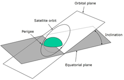
(iv) Tendency (I) is measure of the point between orbital and tropical planes of earth at the climbing hub with heading being east to north.
The point of tendency are
(i) Equatorial circle (the angle of tendency = 0 degrees or 180 degree).
(ii) Polar circle (the angle of tendency is 90 degrees).
(iii) Prograde circle (the angle of tendency in between zero and 90 degrees).
(iv) Retrograde circle (the angle of tendency in between 90 and 180 degrees).
CALCULATION:
Walker constellation design equation is i: t/p/f
Where, i= inclination
t = total number of satellites = 2
p = number of equally spaced orbit planes = 2
f = relative phase difference between satellites in adjacent planes = 120o
Then, i = 2/2/120o
ENDLESS SUPPORT IN UFMFLN-15-3 SATELLITE COMMUNICATIONS ASSIGNMENTS WRITING SERVICES - YOU GET REVISED OR MODIFIED WORK TILL YOU ARE SATISFIED WITH OUR UFMFLN-15-3 SATELLITE COMMUNICATIONS ASSIGNMENT HELP SERVICES!
BLOCK DIAGRAM OF EARTH STATION
Designing of an Earth station relies upon now not solely on the place of earth station but additionally on some other factors. The location of earth stations may want to be on land, on ships in sea and on aircraft. The depending elements are the type of service providing, frequency bands utilization, transmitter, receiver and antenna characteristics.
The block diagram of the digital earth station is proven in under figure.
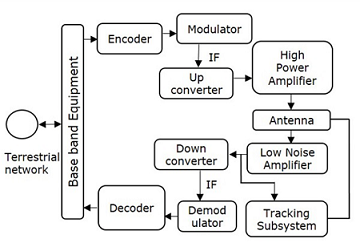
We can effortlessly apprehend the working of earth station from above figure. There are four main subsystems that are existing in any earth station. Those are a transmitter, receiver, antenna and monitoring subsystem.
TRANSMITTER: The encoder incorporates blunder review bits in order to urge the bit ruin rate. In satellite TV for pc correspondence, the Intermediate Frequency (IF) can be picked as 70 MHz by strategies for the usage of a transponder having an exchange speed of 36 MHz.
The earth station receiving wire transmits this sign.
RECEIVER: This is a low-level changed RF signal. Precisely when all is said in done, the got sign will have less sign quality. As needs be, to expand this sign, Low Noise Amplifier (LNA) is used. Subsequently, there is an update in Signal to Noise Ratio (SNR) regard.
RF sign can be down changed to the Intermediate Frequency (IF) regard, which is either 70 or a hundred and forty MHz. Since, it is unquestionably not difficult to demodulate at these moderate frequencies. The section of the decoder is just converse to that of an encoder. In this manner, the decoder passes on a mess up free organized data by techniques for disposing of mess up change bits and altering the bit positions foreseeing any. These twofold certifications are given to baseband equipments for further overseeing and after that offering you to terrestrial framework.
EARTH STATION ANTENNA: The earth station gathering mechanical assemblages are legitimate for both transmitting and getting electromagnetic waves. Figurative reflectors are used as the exceptional receiving wire in earth stations. To get of these reflectors is high. They have the limit of focusing a parallel fragment into a point at inside, the see the feed contraption is found.
TRACKING SUBSYSTEM: Following subsystem keeps up track with the satellite TV for pc and affirmation that the segment comes towards it to set up the correspondence. The Tracking contraption current in the earth station executes as a last resort two functions. Those are satellite getting and following of satellite. A mesh type reflector can be used for focusing the alerts into a twin feed-horn. It is having two separate outputs. From one output will get C-band indicators and from other output will get Ku-band signals.Television programming basically originates as first technology signals. These signals are transmitted through satellite to network principal end stations in C band. These signals are compressed and transmitted in digital shape to cable and DBS providers.C-band users can subscribe to pay TV channels. These subscription offerings are more cost effective when compared to cable due to the fact of the availability of multiple-source programming.
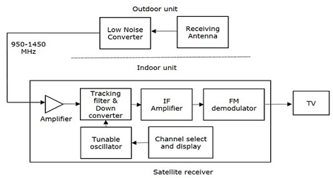
The block layout of DBS TV receiver is shown in below figure.
HELPING STUDENTS TO WRITE QUALITY UFMFLN-15-3 SATELLITE COMMUNICATIONS ASSIGNMENT AT LOW COST!
OUTDOOR UNIT: Outdoor unit frequently consists of receiving antenna and Low Noise Converter (LNC). Low Noise Converter (LNC) is nothing but the combination of Low Noise Amplifier (LNA) accompanied by using a converter. The receiving antenna is directly fed into LNC. In general, the parabolic reflector is also used with the receiving horn antenna for greater focusing of the beam.
INDOOR UNIT: In general, the sign fed to the indoor unit is a wideband signal. The frequency of this signal lies between 950 MHz and 1450 MHz In indoor unit, this signal receives amplified with the aid of the use of an amplifier. This is the predominant distinction between DBS TV and conventional TV.
CALCULATION:
Let No. of satellites = 25
Orbit plane separated by 120o
And orbit planes = 3
Phase shift = 60/3 = 20
Inclination = 60o
Phase shift between the adjacent orbits = f X 60o/3 = 20o
This is done by using the Galileo constellation formula.
Let the power = 100kW for altitude = 750km
Then SNR =power/(altitude3) = 100000/7503 = 100/753
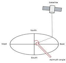
The formula for Azimuth angle (α) is = 180o + tan-1(tan(G)/tan(L))
Where, L = Latitude of earth station antenna = 750km
And G = the difference between position of satellite orbit and earth station antenna = 150
Therefore, Azimuth angle (α) = 180o + tan-1(0.26/0.58)
= 180o + tan-1 (0.44)
= 180o + 23.75o
= 203.75o
GET READYMADE UFMFLN-15-3 SATELLITE COMMUNICATIONS ASSIGNMENT SOLUTIONS - 100% PLAGIARISM FREE WORK DOCUMENT AT NOMINAL CHARGES!
5. SATELLITE COMMUNICATION - KEPLER'S LAWS
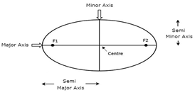
KEPLER'S FIRST LAW: The path traced by satellite when it revolves around earth will be an oval. There are 2 focuses called foci associated with this oval, namely F1 and F2 as per the figure shown herewith. Focus of mass of the earth will constantly display at one of the two foci of the oval.
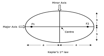
Apogee is the measure of the separation from the focal point of the article to a point on its circular way.
KEPLER'S SECOND LAW: For equivalent interims of time, the territory secured by the satellite will be same as for focus of mass of the earth. This can be comprehended by investigating the accompanying figure.
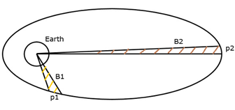
Accept, the satellite spreads p1 and p2 separates in a similar time interim. At that point, the zones B1 and B2 secured by the satellite at those two cases are equivalent.
KEPLER'S THIRD LAW: The shape of its semi real pivot length andthe square of the associated time of a circular circle are interrelated.
EARTH ORBIT SATELLITES
Following are the three significant sorts of Earth Orbit satellites -
- Geosynchronous Earth Orbit Satellites
- Mid-level Earth Orbit Satellites
- Low Earth Orbit Satellites
GEOSYNCHRONOUS EARTH ORBITSATELLITES
Important characteristics of this satellites are:
- Altitude = 22,300 miles from the earth surface and
- Altitude = 35,900 kms from the equator of the earth.
The used of it found in satellite-televisions. There is a 4 minutes interval between satellite and earth rotation as the path is not round.
THE BENEFIT OF GEOSTATIONARY CIRCLE:
The use of Geo-stationary orbit found in transmission of radio signals, TV signals and climate prediction.
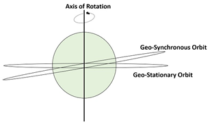
Fig: difference between the Geo-synchronous and Geo-stationary orbits
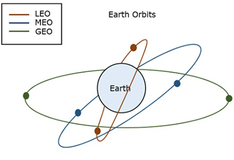
Fig: The paths of LEO, MEO and GEO
COMMUNITY ANTENNA TV SYSTEM
The Community Antenna TV (CATV) system has application in single outside unit. Here no need of separate receiver for every user.
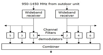
Fig: Block diagram of indoor unit of CATV device
SATELLITE COMMUNICATION LINK SERVICES:
One-way: point-to-point and point-to-multipoint connectivity present.
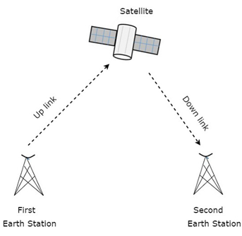
Example: Radio, TV.
Two-way: only point-to-point connectivity present.
Example: Telephone, Fax.
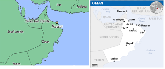
5. Location of receiver in Muscat, Oman
MOST RELIABLE AND TRUSTWORTHY UFMFLN-15-3 SATELLITE COMMUNICATIONS ASSIGNMENT HELP & HOMEWORK WRITING SERVICES AT YOUR DOORSTEPS!
Access our University of the West of England, UK Assignment Help Services for its related units such as:-
- UFMFX8-30-3 Individual Project Assignment Help
- UFMFS7-15-3 Communications Assignment Help
- UFCF95-15-3 Entrepreneurial Skills Assignment Help
- UFMFJN-15-3 Radio Frequency and Microwaves Circuit Design Assignment Help
- UFMFKN-15-3 Mobile and Wireless Communication Assignment Help
- UFMFV8-15-3 Group Design & Integration Project Assignment Help
- UFMFH8-15-3 Digital Signal Processing Assignment Help
- UFMFW7-15-3 Control System Design Assignment Help
- UFMFD7-15-3 Energy Technologies Assignment Help
- UFMFE8-30-2 Digital Design Assignment Help
- UFMFQ8-30-2 Electrical Technology Assignment Help
- UFMFJ8-15-2 Drives and Motions Assignment Help
- UFMFR7-15-2 Communications, Signals and Filters Assignment Help
- UFMFRJ-15-2 Power Systems Fundamentals Assignment Help