DO YOU WANT TO EXCEL IN STAR - DELTA CONNECTION ASSIGNMENT? HIRE TRUSTED TUTORS FROM EXPERTSMINDS AND ACHIEVE SUCCESS!
Q1. For a Yd1 transformer:
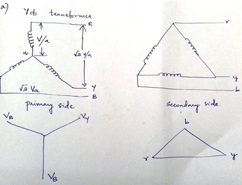
(a) Draw the connection diagram
The Star - Delta connection is shown below

(b) Show how the connections must be modified to allow parallel operation with a Yd11 transformer.
Yd11 - Here 11 represents the phase displacement. This is between the HV and LV windings.
11 = 330o lagging or 30o leading

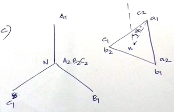
(c) Draw a phasor diagram for the modified connection.

EXPERTSMINDS.COM ACCEPTS INSTANT AND SHORT DEADLINES ORDER FOR STAR - DELTA CONNECTION ASSIGNMENT - ORDER TODAY FOR EXCELLENCE!
Q2. In your own words, state the three essential and two highly desirable conditions which must be fulfilled for two 3-phase transformers to operate satisfactorily in parallel. State briefly what you think may be the possible consequences of not complying with these conditions.
The assumptions are
a) Both the transformers should have same phase shift.
b) Paralleling via distribution or transmission circuits which consists of cables and overhead lines.
c) When connected in no phase shift condition the primary and secondary are in phase. But when connected differently, the secondary voltage waveforms will differ from the primary voltage waveforms by 30 degrees. And is called a 30 degree phase shift. Parallel connected transformers will have same phase shift.
d) For satisfactory operation the voltage ratios could be same
e) The leakage impedance is inversely proportional to the KVA rating
f) Proper connection of transformers that means the polarities is more important. If polarities are reversed it can lead to damage of transformer.
NEVER LOSE YOUR CHANCE TO EXCEL IN STAR - DELTA CONNECTION ASSIGNMENT - HIRE BEST QUALITY TUTOR FOR ASSIGNMENT HELP!
Q3. (a) Two single-phase transformers have the following impedances referred to the secondary side. Unit A rated 250 kVA (0.09 + j2.7) Ω Unit B rated 400 kVA (0.04 + j1.6) Ω. Determine the load taken by each machine as a percentage of its rating when they share a common load of 500 kVA at 0.73 p.f. lag.
To calculate -
Unit A rated 250 kVA (0.09 + j2.7) Ω
Unit B rated 400 kVA (0.04 + j1.6) Ω
Common load of 500 kVA at 0.73 p.f. lag
|
Unit A
|
Unit B
|
|
(0.09 + j2.7) Ω =2.7015L30
|
(0.04 + j1.6) Ω
|
|
Choose a base = (250/400)x(0.04 + j1.6)
0.625(0.04 + j1.6) = 0.025+ j1
= 1.0003L40
|
|
The load taken by each machine as a percentage of its rating
|
|
S = 250x(2.7015/1.0003) = 675.17KVA
|
S = 400x(2.7015/1.0003) = 675.17KVA = 1080.27KVA
|
Q3. (b) Transformer A is rated at 300 kVA with an impedance of (0.09 + j0.18) Ω. Transformer B is rated at 200 kVA with an impedance of (0.09 + j0.23) Ω. If these transformers are connected in parallel to supply a common load, determine the percentage overload on B when A supplies its full load at p.f. 0.45 lag.
To calculate -
Transformer A is rated at 300 kVA with an impedance of (0.09 + j0.18) Ω.
Transformer B is rated at 200 kVA with an impedance of (0.09 + j0.23) Ω.
|
Transformer A
|
Transformer B
|
|
(0.09 + j0.18) Ω = 0.2012L61.36
|
(0.09 + j0.23) Ω
|
|
Choose a base = (300/200)x(0.09 + j0.23)
1.5(0.09 + j0.23) = 0.135+ j0.345
= 0.3705L67.63
|
|
The load taken by each machine as a percentage of its rating
|
|
S = 300 x (0.2012/0.3705) = 162.91KVA
|
S = 200x(0.2012/0.3705) = 108.61 KVA
|
ORDER NEW STAR - DELTA CONNECTION ASSIGNMENT & GET 100% ORIGINAL SOLUTION AND QUALITY WRITTEN CONTENTS IN WELL FORMATS AND PROPER REFERENCING.
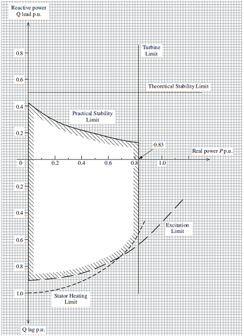
Q4. From the operating chart shown determine the following performance limitations for a generator:

(a) where the power limit and the MVA limit coincide;
(i) the power factor = 0.83
(ii) The load angle = 24.59
(iii) The MVAr output = 0.12
(b) where the power limit and the stability margin coincide;
(i) The p.u. excitation = -0.7-j0.83
(ii) The MVA output = √(0.832+.122) = 0.8417.
GET GUARANTEED SATISFACTION OR MONEY BACK UNDER STAR - DELTA CONNECTION ASSIGNMENT HELP SERVICES OF EXPERTSMINDS.COM - ORDER TODAY NEW COPY OF THIS ASSIGNMENT!
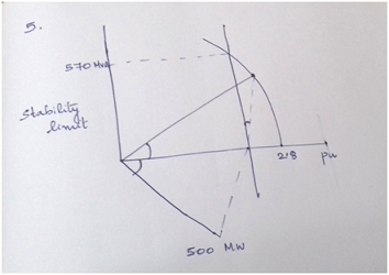
Q5. A 3-phase synchronous generator rated at 570 MVA is connected to an infinite busbar. Using the data given in the table below, plot the capacity chart of the generator.
|
Quantity
|
Value
|
|
Synchronised Reactance
|
2.0 p.u
|
|
Excitation Limit
|
2.8 p.u
|
|
Maximum Margin
|
570 MVA
|
|
Turbine Power Limit
|
500 MW
|
|
Stability Margin
|
10% Full Load Power
|
