NEVER BE CAUGHT IN PLAGIARISM, AVAIL PACKET SWITCHING AND NETWORKING MODELS ASSIGNMENT HELP SERVICE OF EXPERTSMINDS.COM AND SAVE HIGHER MARKS!
Packet Switching and Networking Models Assignment
LO1. Describe and explain the role and function of network connectivity in current computing.
LO2. Describe and explain the principles of communication in networks.
LO3. Describe the role and functionality of hardware and software entities that contribute to network communications.
LO4. Describe and explain the protocols and interactions that implement network communications.
LO5. Describe fundamental aspects of cloud computing.
To encourage students to use content analysis summaries to prepare for tests, examinations and to help their understanding of theoretical concepts.
To encourage students to conduct independent investigation into networking related topics from books, the Internet and through practical investigation.
HELPING STUDENTS TO WRITE QUALITY PACKET SWITCHING AND NETWORKING MODELS ASSIGNMENT AT LOW COST!
1. Overview of ITEC 1102 Networking and Security
A computer network is defined as the exchange of information between the devices that are connected in the network. This is the concept of engineering which analyze the process of communication that is linked together for exchanging of information. There are different types of information exchanged in the network that includes the Google search, sending the file to the printer, eBay, online video call and so on. These examples use the networking in simplest way to improve the technology (Sumit Ahlawat, 2014).
Example of purchasing the product in eBay determines the type of information is exchanged between the devices. The product is viewed in the eBay and chooses the product and checkout, sign to the login page and pay the amount through PayPal. This transaction takes place using Cat6 cables where the pair of cables is twisted together with the number of correct twist present in the cable. The computer must connect with if the cable is disconnected. Many number of devices like PayPal server, bank server, desktop eBay server may be used for exchanging.
This session are specifically deals with the networking technologies and the tool talks like Linux networking tools, windows networking tools and windows calculator. There are four types of number system in networking. Decimal represents the IPv4 address, Binary used for enquiring the bits, Hexadecimal represent the IPv6 and the octal used for Linux permission. The binary number system is the best when compared to all other number system. The base values and the valid digits for the number system are defined as in the table.

Figure 1: Valid Number System
The binary number is denoted in form of 0 and 1.Conversion of a number from binary to decimal, decimal to binary. The hexadecimal number is used for larger number that is frequently used.
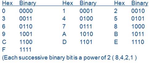
Figure 2: Hexadecimal to Binary
The above figure2 shows the conversion of hexadecimal value to binary values. The binary equivalent octal number is shown in figure 3.
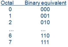
Figure 3: Octal to Binary
The windows calculator program is used to convert the defined quantity to different number system by running the tool in run calculator. The demonstration is shown in figure 4.
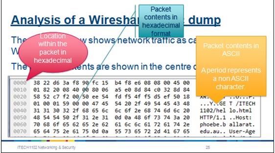
Figure 4: Wireshark
GET READYMADE PACKET SWITCHING AND NETWORKING MODELS ASSIGNMENT SOLUTIONS - 100% PLAGIARISM FREE WORK DOCUMENT AT NOMINAL CHARGES!
2. Packet Switching & Networking Models
The packet switching and circuit switching were the two switching modes which are used for connecting the multiple communicating the devices with each other. The circuit switching is connection oriented whereas the packet switching is connection less and used for communicating in transmission mode. The packet switching is initially designed for the transmission of the data which is very flexible to find the route to travel from the source to the destination. Packet switching is used in two approach including the datagram approach and circuit approach and is implemented in network layer (Mutha, 2012).
When the packet is transmitted in packet switching mode which defines the manageable parts called as packets. The packets are transmitted from source to destination which is assembled before the destination is reached. This interface message processor was implemented to do the work of router in olden days. This packet switching relies on the concept of packet fragmentation and reassembly. If the packet is damaged or there is congestion that makes the packet to be lost and change the sequence of packet. Packet switching is used in home network and in the telephone system.

Figure 5: Router
The Ethernet hub is used for connecting the devices in the network to exchange the information. The switches are the smart device that connect the devices in the network and direct the traffic to the destination. A router provides the internet connection that has two network cards for communicating with the other networks. The networking topologies are explained using the reference networks. The home based networks are tablet, PC, internet, TV, Phone, Fridge and Security camera and so on. The common technology includes the encryption of data and low transmission of power. The reference home network is shown in the figure 6.
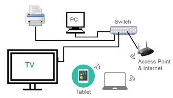
Figure 6: Reference Home
The campus network is exercise discuss in the class about the functionality of the type of networks. The eBay purchase system is demonstrated with the cable from the PC linked to switch in the network for the transaction. To understand the various problems in networking, Divide and Conquer method are used and to make the network in the simplest form, the OSI Reference Model and Internet Model are used (Nitish Aggarwal, 2014).
The Internet model is the framework to understand the working of TCP/IP. These two protocols are used in the network to avoid the traffic in network. The other protocols are used over the decade of years whereas the TCP/IP is used nowadays. The OSI model has seven layers that transmit the data from physical layer to the application layers. The OSI model is related to TCP/IP model as shown in figure 7.
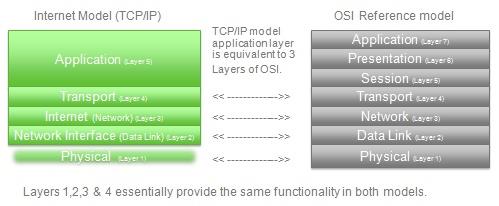
Figure 7: OSI model is related to TCP/IP model
MOST RELIABLE AND TRUSTWORTHY PACKET SWITCHING AND NETWORKING MODELS ASSIGNMENT HELP & HOMEWORK WRITING SERVICES AT YOUR DOORSTEPS!
3. The Application layer (Layer 5)
The application layer is the top layer in OSI model that manipulates the information in different forms to access the network. The services provided by this layer are E-mail, file transfer, directory services, network resources, distributing the files, face book and Google search. This layer consists of number of protocols used by the users (Hawkar H. Khalil, 2015). One such protocol is hypertext transfer protocol that is used in World Wide Web and the other protocols include FTP, TFTP, SMTP, TELNET and DNS.
The different functions of the application layer are Mail Services, Network Virtual Terminal, Directory Services and File transfer, access and management. The email is stored and forwarded using mail services. The logging the remote host by the user to access the terminal is done through virtual terminal. Accessing of global information is done in directory services. The standard mechanism is followed for managing and accessing the files using FTAM.
Client Server Architecture
The server will wait until it receives the request from the client and reply to those request. The authentication may require by some server for processing to those request. The server runs on the service to access the request. The client is the customer and the server is the provider to access the services in the web.
Peer to Peer Architecture
The device itself will act as both the server and the client to share the resources and so there is no need to use the particular server. This type of network architecture will work in small and home networks. All the works are distributed to all devices as these devices acts as server and the client.
Host based Architecture
This architecture is familiar in olden days by using mainframe technologies. The mainframe system is used in transaction processing, bank transaction, airline transaction and the insurance transaction (Sunil Kumar, 2011).
Cloud based Architecture
The cloud based system defines the services, applications and the resources that are available for the user to demand the internet from the cloud providers. The cloud service provides the cloud based architecture which increases the capacity, functionality and the services. There are different components of cloud architecture are cloud resources, software components and the middleware. Cloud defines the components and the relationship between those components.
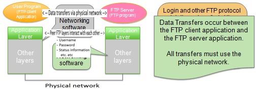
Figure 8: Client and Server application interaction
Infrastructure as a Service
This is the instant service providing the infrastructure, provisioned and managed in the internet. Based on the demand the service may scale up and down depends on the complexity of the infrastructure. The service providers like Azure manages and configure the infrastructure of the software.
Platform as a Service
This service provides the components to use in the application and other development of the software. This PAAS provides the development, testing, deployment with simple and cost effective technology. Macros are created and stored in the Excel.
Software as a Service
Software as a service provides the largest market in the cloud which is growing still. This service uses the web browser to develop the application and manage by third party vendor. SaaS eliminates the installation process when the execution takes place.
Network Protocols
All the above mentioned protocols are described for the transfer of files like FTP and HTTP.
HTTP is used for web application and the FTP is used for file transfer between the client and the server.
Protocol Headers
Protocol headers are added to the each layer when the data is passed through the protocol stack which transmits TCP header, IP header and the Ethernet header.
SAVE DISTINCTION MARKS IN EACH PACKET SWITCHING AND NETWORKING MODELS ASSIGNMENT WHICH IS WRITTEN BY OUR PROFESSIONAL WRITER!
4. The Data link layer (Layer 2)
The data link layer is the second layer in the OSI model which is used to define the operating system for the networks. The main functions of this data link layer is transmission of the errors, flow of data is regulated which provide the interface to the network or internet layer. When the data is transferred to the internet layer the data link layer checks the timer and sequence number to check whether there is any error when data is transmitted successfully. There are certain rules and regulation to define the protocol to complete the task to transfer the data to the network layer.
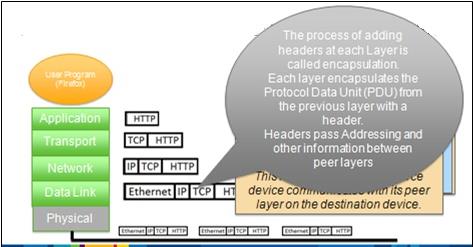
Figure 9: Data Link Layer
The network interface card is used to connect the network with other connections which interfaces the printers, scanners, routers and other network devices. The NIC have unique 48 bit MAC address that interface the manufacturer to exchange the source and the destination MAC address for communication. The network is determined with MAC address to configure the network setting including IPv4 and IPv6.

Figure 10: Format of Ethernet Frames
The cyclic redundancy check is used to check the error in the information using the NIC. The error is checked at the sending and receiving end and if there is any difference which means the packet is corrupted and discarded. The Ethernet frame consists of payload from all layers to identify the destination of the information. The Ethernet is defined with the frames of the destination MAC address to drop the unwanted frames
Broadcasting
The destination MAC address in a frame is all binary 1 that is processed in the local networks. The hexadecimal broadcast address is FF FF FF FF FF FF FF FF which is 48 bits.
Media Access Control
Media access control is used to share the media in two categories including the controlled access and the contention based access. The single device is transmitted at a time in controlled access (Wen Zeng, 2015). The examples of Media Access Control are Token ring and the FDDI. The connection based media access control is CSMA/CD used for Ethernet networks and CSMA/CA used for 802.11 wireless networks.
CSMA/CD
Carrier Sense Multiple Access with collision detection is the media access protocol used by the router (Ethernet). This is widely used in the data link layer to connect the devices in the network. Collision is occurred when two or more devices request the Ethernet simultaneously.
CSMA/CA
Carrier Sense Multiple Access with collision avoidance is similar to the CSMA/CD that avoids the collision by reserving the network media before transmission of data the request is sent to wireless access point and clear to send to wireless network without the collision.
Local Address Resolution
The local address is done in internet protocol called as address resolution protocol that is used to determine the MAC address of the system in the network, if the device does not know the MAC address of the requested system (S.Venkatramulu, 2013).
ARP
The network maintains the table in random access memory to use the MAC address and the IP address that is present in ARP cache. This table not too large to access the particular IP that uses the Ethernet frame. The data link layer is responsible for the exchanging the information between the devices connected in the network.
EXPERTSMINDS.COM GIVES ACCOUNTABILITY OF YOUR TIME AND MONEY - AVAIL TOP RESULTS ORIGINATED PACKET SWITCHING AND NETWORKING MODELS ASSIGNMENT HELP SERVICES AT BEST RATES!
5. The internet (Network) layer (Layer 3)
The ARP determines the MAC address with the help of IP address. The ARP window is used to observe the cache content and delete the entry and then finally delete all the ARP entry. As per the ARP commands some of the entries will remain the same due to different functions. The syntax of the Linux is different from other as it is not required in the ARP cache. After the successful of using ARP command, the new MAC address is paired to add in the ARP cache which will be deletes after certain period of time. The data link layer is defined to transfer the data from the router to the internet to access the information in the network layer.
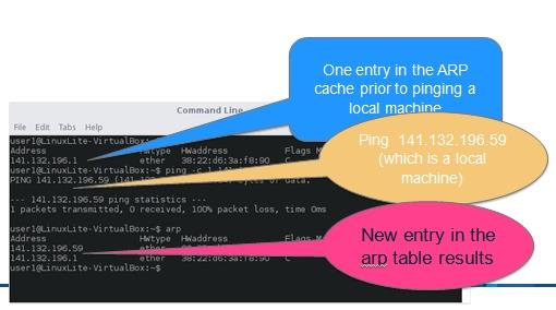
Figure 11: ARP cache
The role of network layer is to transmit the information between the host to host environments where these two hosts are separated by long distances. The network layer describes the IP addressing and the routing. The IPv4 and IPv6 are the two types of IP addressing. When considering the IPv4, the IP address of the other devices connected in the network is identified.
Structure of IPv4 address
IPv4 is 32 bit addressing which separates the bits into 4 lots of 8 bit called octet expressed between 0 and 255. The IP address is configured manually or automatically. The IP address is assigned manually in Manual administration and the system allocates the IP address using DHCP. The IP address contains Networks bit and Node bits (Henry Chukwuemeka Paul, 2016).
Subnet Mask
The subnet mask is available with all the system in the network. This mask provides the number of bits in the IP address and the number of nodes. There are two methods used to determine the IP address. If all the node bits are identified as the zeros then the IP address is received. If bitwise operators are carried out within the subnet mask to get the IP addresses.
Classless inter domain routing
The other method to represent the number of bit in IP address is by using CIDR notation. If the address of the source and the destination is same then the communication is sent directly to the destination device. If it is different then it is sent to the network router.
IP addressing
There are two types of addressing. Public and Private addressing. The public addressing is used within the internet. The private addressing is removed from the routers. The range of private address is varied depends on the network.
Network Address Translation
The device of home network is connected to the private IP address using network address translation to access the internet. This is achieved by changing the IP address of the Internet Service Provider.
| Network address |
Interface |
Next Hop |
| 141.132.64.0 |
141.132.64.1 |
141.132.64.1 |
| 141.132.192.0 |
141.132.64.1 |
141.132.64.3 |
| 141.132.128 |
141.132.64.2 |
141.132.64.2 |
| 141.132.192 |
141.132.64.1 |
141.132.64.3 |
Figure 12: Routing Table
When the packet is arrived to the network, the interface is identified along with the next hop from the source to the destination. The routing table defines the next hop along with the interface and the network address. The Open Shortest Path First, Routing Information Protocol and Border Gateway Protocols are commonly used routing protocols.
ENROL WITH PACKET SWITCHING AND NETWORKING MODELS ASSIGNMENT HELP AND HOMEWORK WRITING SERVICES OF EXPERTSMINDS.COM AND GET BETTER RESULTS IN PACKET SWITCHING AND NETWORKING MODELS ASSIGNMENTS!
6. The transport Layer (Layer 4)
The different port addresses are specified in the transport layer that uses the server application. The protocols used in the transport layer are TCP segment and UDP Datagram. The numbers of browsers or email are accessed simultaneously using the transport protocol.
Segmentation and Reassembly
When the large amount of data is delivered or transmitted using the web applications in transport protocols. The transport layer breaks the large amount of data to manage the small segments to access the network. The segmented data at the destination is reassembled to transmit the information to the next layer which is called as reassembly. The reassembling of data is ordered in the order of delivery.
Identification of Application
When the multiple applications are opened at the time to execute, the transport layer allocates the port number for each client to run all the application in the same system. The combination of IP address along with the port number is specified for accessing the application in the system. Each device is noted with separate IP address and each client is identified by the unique port number.

Figure 13: IP addresses, Ports and Sockets
The server port numbers are reserved for server daemons. There are 1024 ports (0-1023) used in specific server application. When the port is connected to the network, the user application is dynamically selected from the unused port number beyond 1023.
UDP
User datagram protocol is the basic transport service used in network application specifying the source and destination port number, checksum and the length of UDP header (Sangeeta Yadav, 2014). UDP is a stateless protocol where no verification is done to identify whether the packets arrived safely. This protocol consists of pair of request and response in the individual transaction.
TCP
Transmission control Protocol is connection oriented protocol that relies on network with order of the data delivered from sender to the receiver. The connection must be established before sending of information from sender to the receiver. The tracking of data is done using the sequence number. Once the information is received in the receiver end, the acknowledgement is used throughout the session. The TCP timer is used to identify the lost or damaged segment in Transport layer (Albandari Mishal Alotaibi, 2017).
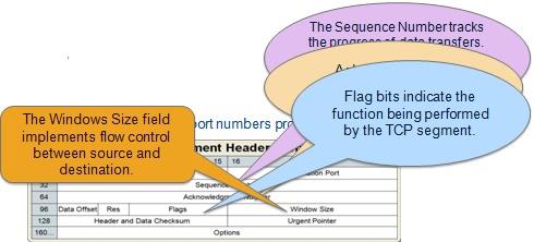
Figure 14: Transmission Control Protocol
TCP Connection Establishment and Termination
The connection is established before the transmission and the duration of the session lost for transmission time and terminates automatically. The TCP connection is done with three way handshaking protocol that facilitates the end to end connection with initial sequence number between the client and the server.
Three Way handshaking
The client initiates using SYN flag and the server responds to SYN and ACK command then with ACK flag.
TCP Flow Control
The flow control is defined by the data from source to the destination with the size of the window to be specified in the TCP header using the mechanism of sliding window flow control.
24/7 AVAILABILITY OF TRUSTED PACKET SWITCHING AND NETWORKING MODELS ASSIGNMENT WRITERS! ORDER ASSIGNMENTS FOR BETTER RESULTS!
7. The physical layer (Layer 1)
The physical layer is the first layer in OSI model which consists of data which is the combination of bits. The data are of two types and they are Analog data and digital data. The text files, songs and videos are analog data whereas the data stored in the hard disk or the floppy discs are analog data. The binary digits are in form of 0 and 1. The analog data is expressed as analog wave where the data is sent to the program called audacity. The digital data are represented in form of 0 and 1 like binary data and the data stored in the computer. The data are transmitted from the source to the destination with the different modes of transmission (Mustafa Jahajee, 2015).
Point to Point communication
The resources are shared between the devices with the Ethernet using hub and the Wi-Fi. The protocols are used for transmitting the data from the system.
The transmission of data may be simplex, half duplex and full duplex for transmitting the data. Simplex is transmitting in single direction, half duplex is one way and full duplex is sending and receiving the data simultaneously in both the direction.
Multiplexing
There are different types of multiplexing like frequency division multiplexing, Wavelength division multiplexing.
Mode of Transmission
There are different modes of transmission either wired transmission or wireless transmission. The transmission may takes place through unshielded twisted pair, shielded twisted pair, coaxial cable, and optical fiber, infrared.
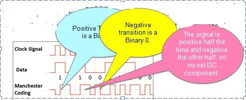
Figure 15: Manchester Encoding
Twisted Pair Cable
There are twisted cable used in telephone network, within the building and the local area networks. This is very cheap, easy to work with this cable, it has low data rate, short range of frequency.

Figure 16: Twisted Pair Cable
Coaxial Cable
This cable consists of two conductors the outer and the inner conductor which is solid metal and is 1 to .5 cm in diameter.
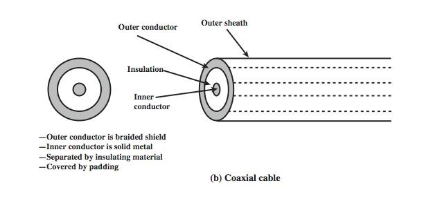
Figure 17: Coaxial Cable
Optical Fiber
This consists of core, cladding and the jacket which is made of plastic and it transmits the light emitting diode and is specially designed for transmission.
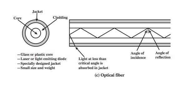
Figure 18: Optical Fiber
The satellite point to point communication link is used to transmit the information using the broadcasting the data. The infrared transmission is end line of sight with no license used in TV remote control and the Infrared Port.
GET ASSURED A++ GRADE IN EACH PACKET SWITCHING AND NETWORKING MODELS ASSIGNMENT ORDER - ORDER FOR ORIGINALLY WRITTEN SOLUTIONS!
8. Cloud and mobile
A cloud computing is defined as the on demand request of the computer to access the resources and the data are stored in the data center to access the data whenever it is requested. The different cloud is used nowadays such as Google drive, face book, drop box and apple cloud which stores large amount of data in the cloud data center. Most of the cloud us sued for the storage services in the data center which has no limits to store the data. The Fed Uni cloud services are the cloud services that have hundreds of services running in the cloud server. Some of the cloud service is swifted to the service providers (Jesus Carretero, 2014).Azure cloud is used in much service with number of servers to perform multiple tasks. The hosting station includes identity management and the workstation.
Advantages and Disadvantages of Cloud
Advantages
Deployment is immediate, Removing of infinite resources, Relieves the technical employ and using of virtualization techniques
Disadvantages
Cost is high and the Cost depends on CPU, power used, capacity and backup
Virtualization Architecture
The device where the virtualization software is executing is called the host system. The virtual OS called as guests. The Virtual box is used which is of two types. There are two types of virtualization including type 1 architecture and type 2 architecture.
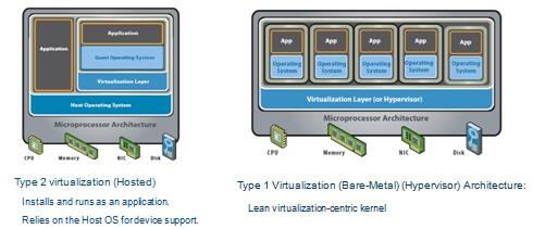
Figure 19: Virtualization Architecture
Mobile Computing
The networking is specially designed for the mobile phone based on the different technologies. They are 1G, 2G, 3G, 4G and then 5G in future. 2G is Global system for mobile communication designed or CDMA based. 3G introduces the high speed networking based on CDMA. 4G based on higher data rate. 5G is underdevelopment used in future (Vora, 2015).
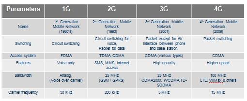
Figure 20: 1G to 4G Technology
Moving from Cell to Cell
The mobile phone will be moved from one place to other which automatically moves from one cell of the base station to the other cell of other base station.
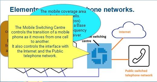
The TDMA and CDMA are digital techniques which are used in mobile handoff to transfer the data called as chipping code.
NO PLAGIARISM POLICY - ORDER NEW PACKET SWITCHING AND NETWORKING MODELS ASSIGNMENT & GET WELL WRITTEN SOLUTIONS DOCUMENTS WITH FREE TURNTIN REPORT!
Access Federation University Assignment Help Service for its related units and courses such as:-
- ITECH1100 Understanding the Digital Revolution Assignment Help
- ITECH2004 Data Modelling Assignment Help
- ITECH2000 Mobile Development Fundamentals Assignment Help
- ITECH1103 Big Data & Analytics Assignment Help
- ITECH1104 Cloud & Enterprise Computing Assignment Help
- ITECH2002 Systems Modelling Assignment Help
- ITECH1001 Communications & Technology Assignment Help
- ITECH3000 IT Professional Engagement Assignment Help
- ITECH3001 User Experience Assignment Help
- ITECH1101 IT Problem Solving Assignment Help