Module: 55-701475 Equipment Engineering and Design
Assignment Title: Vibrations and Structures Case Study
Sheffield Hallam University
Module learning outcomes to be assessed:
• Analyse the performance and reliability of machines.
• Design systems for maintenance, reliability and good performance.
• Propose and justify measurement and monitoring systems for plant.
• Predict the behaviour of mechanical engineering systems
• Criticise the design and implementation of machine systems from cost and efficiency standpoints.
Task 2 - (A) - Vibration Case Study
Excessive vibration in a fan
Questions
Question 1. What are the likely causes of the vibration problems?
Answer: Likely causes of the vibration problems are as follows,
1) As the inlet vanes are closed for the fans, there is excess pressure build up in the system, as there is no proper air flow into and out to the atmosphere, the Ventilation fan is likely to get vibrations(Osinki,2017).
2) It is possible that the body frame of the vibration fan is not properly bolted with the foundation bolts and hence it may be creating excessive vibrations during the fan operations.
3) The grounting between the pedestal and the foundation has reported to get disintegrated, even this is causing clearance and related vibrations in the vibration fan during the actual operations.
4) Shaft surfaces got worn out, where the bearings are located, hence the clearance between the bearings and the shaft is making the fan body to vibrate during the actual operations of the fans.
5) Also it is observed from the vibration amplitudes progressive increase with the height, that the bolt is not actually located in the ground properly, the clearance between the bolt and the ground is increasing gradually and hence the bolt is vibrating with time. Centrifugal pump body is vibrating due to this reason. The bolt need to be located firmly in ground and it is required that there is no gap between the bolt and the ground during installation.
Order New 55-701475 Equipment Engineering And Design Course Assignment!!!
Question 2. What would you, as plant engineer, recommend to prevent recurrence?
Answer: Recommendations:
1) There is need to inspect the complete assembly of the structure.
2) The complete clearances from top to bottom need to be verified.
3) It is required to make the bolt and the ground clearance become zero.
4) There should be investigation for possible other sources of vibration, like bolt damages, main body fasteners getting lossened.
5) Also impeller alignment need to be inspected.
6) Desing safe speed of the centrifugal fan need to be verified against the actual operating speed of the centrifugal fan.
7) There are multiple v belts employed for the power transmission. The slack of the v-belts need to be verified. Also it is required to inspect whether the slack is uniform in all the V-belts installed on the Centrifugal fan.
8) Bearings need to be verified for the deposit of dirt and other related content. Balls in the bearings and their wear need to be inspected for possible clearance and subsequent vibration.
9) All the moving parts of the centrifugal fan need to be insptected for tightness.
10) Closures of the fan need tobe inspected for the possible deposition of the dirt, other types of blockages.
11) There is damage observed at the locations where the bearings are placed on the shaft, this damage is possibly due to the misalignment of the shaft between the two bearings, Hence the installation of the shaft need to be inspected for the sake of alignment of the shaft in the bearings.
12) Also the desing of the centrifugal fan need to be verified for the possible leakage of the air into the centrifugal fan, from the clearances. There should not be leakages apart from the designated air inlet flows into the main body suction channels. Similarly the delivery need to be from the main outlet channel. Any deviations from the design will disturb the structural balances and will cause vibrations.
13) The overall tightness of the fasteners of the centrifugal pump main body with the pedestal and other supporting means need to be verified for their tightness, if they are not properly clamped, then obviously there will be vibrations.
Other possible recommendations include periodic inspection of the entire body, daily monitoring of the vibration levels in the device, inspecting the flow inlet channels for the sake of grit and other possible blockages. If there anything found, they need to be inspected and removed off. Also the bearings of the centrifugal pump and the impeller need to be verified for greasing and occasionally they need to be lubricated for better functioning of the centrifugal fan without vibrations.
Hire the best and professional UK Writers for 55-701475 Equipment Engineering and Design Assignment Help to boost your grades!!
Task 2 - Part B - Structural Failure Case Study
Background
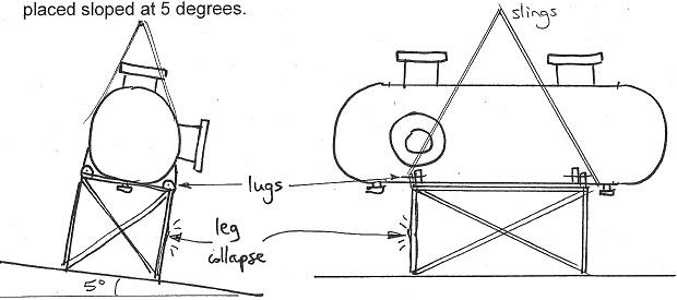
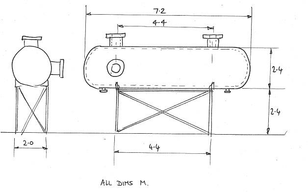
A 6 ton pressure vessel - see Figure 2 dimensioned drawing - was being lowered onto a "stillage" or temporary supporting structure for testing outside a factory in the open yard. The lower lugs were attached to the stillage and as the slings were being loosened by the crane operator, the vessel tilted slightly.
At this point one of the legs of the stillage collapsed. Luckily the slings had not been removed, so the vessel did not fall - but a serious accident was only narrowly averted.
figure was subsequently noticed that the ground on which the vessel and stillage were being placed sloped at 5 degrees.

Figure 1

Figure 2
Question 1. Why did the leg collapse? What effects or details did the designer ignore?
Answer: During the installation process, the leg collapsed because of the fact that the entire load did not get uniformly distributed rather the load is now shifted to one of its legs. The leg could not actually take up the load as it is not designed for the total load of the vessel, it is expected to share only 1/4th of the total load. Due to sloping the actual load acting on the leg is increased than the design load and hence the euler's buckling load exceeding the critical load leading to the collapse of the leg. The designer obviously missed to employ the factor of safety in the design of the leg dimensions and hence the leg collapsed.
Achieve A++ grades by taking our 55-701475 equipment engineering and design assignment help service
Question 2. Redesign the stillage to avoid similar incidents in future, without increasing its footprint (width, length) since space is needed around it for testing.
Answer: Redesigning obviously need to consider the dimensions of the rolled steel angles used for the support of the tank. The section is expected to be provided with the increase in the thickness to support the increased load acting on the lug. The steel angle dimensions are 50x 50x 5 mm.
Hence the cross sectional area of the angle = 500square mm.
The area moment of inertia = 147135.42 mm4
Height of the column = 2.4m
Considering the L shaped column - the area moment of inertia of the column is 147135mm4. = 0.147*10-6 m4
Length of the column = 2.4m
Young's modulus of elasticity = 275Mpa.
Theoretical critical load = 69.3 N
If considering young's modulus only half of the actual yield stress given 137.5Mpa,
The actual critical load = 34.7N
Critical load is calculated from the equation (Alghamdi, 2017),
Fcr = ElΠ2/Leff2
Actual load of the tank = 6000kg = 600N
Acceleration due to gravity = 9.81m/s2 (~10m/s2)
Assuming 4 legs taking up equal loads, the load on each leg = 150N
So the thickness of the leg needs to be redesigned to take up critical load higher than 150 N along with factor of safety more than 2 so 300N
For critical load to be 300N,
The required Moment of inertia = 1.27 *10-6 m4
For such moment of inertia the thickness can be increased to 10mm and the new width of each angle side can be increased to 60 mm
So new dimensions can be 60*60*10mm
However the actual width and height of the stillage need not required to be changed for.
Download New copy of 55-701475 Equipment Engineering And Design Course Assignment!!!
Question 3. Make recommendations on safe lifting and mechanical handling of the vessel.
Answer: Recommendations for safe lifting include making the strings with extra thickness to avoid breakage and subsequent fall of the set-up.
Also lifting can be done separately for the stillage and then the vessel. This will make sure the vessel always sits on the stillage which is quite horizontally located on the ground.
The vessel when is being lifted with the slings is expected to be lifted with slings having always equally placed lengths so that there won't be any turnover of the vessel during the course of the liftage.
There is need to check the ground level check before installing the vessel along with the stillage, if the ground level is not uniform, it is required to be levelled before installing.
Spirit level or any other ground level indicators can be employed for the sake of ground level check up.
End conditions here in the case are assumed to be hinged at both ends. Since these conditions represents well the given scenario.
Access our Sheffield Hallam University course help and assignment help services for various related courses such as: -
- 55-600100 Advanced Engineering Design Assignment Help
- 55-700697 Competitive Design for Manufacture Assignment Help
- 55-602769 Moulding and Tool Design Assignment Help
- 55-704631 Manufacturing Systems Assignment Help
- 55-404594 Legislative and Business Studies Assignment Help
- 55-605568 Engineering Technical Project Assignment Help
- 55-705241 Engineering Principles Assignment Help
- 55-501364 Engineering Design Applications Assignment Help
- 55-601016 Design Evaluation Methodology Assignment Help
- 55-500714 Computer Aided Manufacture and Engineering Assignment Help