Capacitive Current And Reactance
NEVER LOSE YOUR CHANCE TO EXCEL IN CAPACITIVE CURRENT AND REACTANCE ASSIGNMENT - HIRE BEST QUALITY TUTOR FOR ASSIGNMENT HELP!
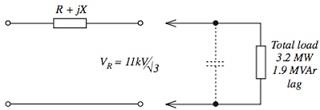
Question: The following phase schematic diagram (FIGURE 4) shows an 11 kV, 50 Hz, 3-phase, short line feeding a load. By calculation or constructing the phasor diagram (use a scale of 1 mm = 2 A) for the load current with VR as reference, determine the capacitive current and
1. Calculate the capacitive reactance/ph such that the load power factor is increased to 0.98 lag
2. Calculate the percentage reduction in line current with this value of capacitive reactance in circuit.
Answer: Conside the figure given below

When voltage and length of the transmission line increases the capacitance has greater importance.
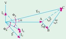
The phasor diagram can be constructed as follows

Receiving End
VR = 11/(√3) KV
Apparent Power = VR IR cos θ
IR = (Apparent Power)/(VR cos θ)
= (3.2 × 10⁶)/[(11 × (1/√3) × 103 × cosθ)
Now Cos θ = KW/(KW + KVAR) = 3.2/(3.2 + 1.9) = 0.6
Now IR = (3.2 × 10⁶)/(11 × (1/√3) × 103 × 0.6) = 629A
As we know Cos θ = IC/IR
So IC = IR × cosθ = 0.6 × 629 = 377.4A
C = (-jIC)/2πf = (-j × 377.4)/(2 × 3.14 × 50) = -j1.20Ω
When load power factor is increased to 0.98 the capacitive reactance can be calculated as follows
IR = (3.2 × 10⁶)/(11 × (1/√3) × 103 ×0.98) = 514A
IC = IR × cosθ = 0.98 × 514 = 503.72A
C = (-jIC)/2πf = (-j × 503.72)/(2 × 3.14 × 50) = -j1.60Ω
Percentage reduction in line current = (624 - 514)/624= 0.17%
ORDER NEW CAPACITIVE CURRENT AND REACTANCE ASSIGNMENT AND GET 100% ORIGINAL SOLUTION AND QUALITY WRITTEN CONTENTS IN WELL FORMATS AND PROPER REFERENCING!