Analog Modulation And Frequency Modulation
MITS5003 Wireless Networks & Communication, Victorian Institute Of Technology, Australia
DO YOU WANT TO EXCEL IN ANALOG MODULATION AND FREQUENCY MODULATION ASSIGNMENT – ORDER AT EXPERTSMINDS!
Question 1: Convert the binary data "110101" into analog waveforms using following modulation techniques:
Given input pattern:

a. Two level Amplitude Shift Keying
Answer: a) ASK output
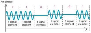
Analog data is generated from the digital data. Here amplitude variation represents the different status of digital data. For zero data in digital mode represent as zero level of amplitude in analog form.The above figure represents the analog form of given binary pattern.
b) Two level Frequency Shift Keying
Answer: BFSK output

This is a modulation method of frequency. Digital data or information passes through the analog carrier frequency by means of discrete frequency variation process. Here space-frequency represents the zero data and mark frequency represents one level of data.The above figure represents the analog form of given binary pattern.
c) Two level Phase Shift Keying
Answer: BPSK output

The above figure represents the analog form of given binary pattern.It is a two way representation of digital data, where for 1 level of digital data output goes to 0 degree and for 0 level of digital data output goes to 180 degrees.
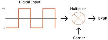
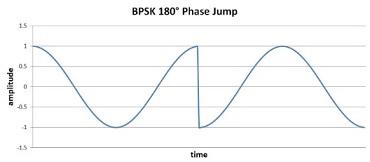
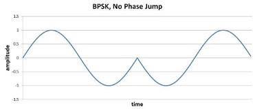
Fig: Representation Of BPSK
WORK TOGETHER WITH EXPERTSMIND’S TUTOR TO ACHIEVE SUCCESS IN ANALOG MODULATION AND FREQUENCY MODULATION ASSIGNMENT!
d) Differential Phase shift keying
Answer: DPSK output

The above figure represents the analog form of given binary pattern.Here modulating signal and the carrier signal shift their phase with 180 degrees. The main advantages of this technique is that oscillator and reference signal are not needed for modulation and also for demodulation.
e) Four level Amplitude Shift Keying
Answer: QASK output:

Here digital data divided in 4 equal parts and then represented in analog form. The above figure represents the analog form of given binary pattern.
f) Four level Phase Shift Keying
Answer: QPSK output

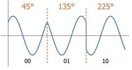
Fig: Representation QPSK
In this form of PSK dual bits are considered for modulation at-a-time. The above figure represents the analog form of given binary pattern
g) Eight level Amplitude Shift Keying
Answer: Eight Level Amplitude Shift Keying Output
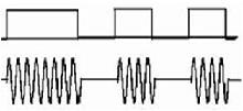
In this techniques amplitude shifted according to the digital input appears. The above figure represents the analog form of given binary pattern
Question 2: With fc = 1000 kHz, fd = 50 kHz, and M = 16 (L = 4 bits), using Multiple Frequency-Shift Keying (MFSK), compute the frequency assignments for each of the sixteen possible 4- bit data combinations.
Answer: MFSK is technique of signal modulation, where data converted from Two-Tone technique to multiple techniques. Here error is less.

Given
‘fc ‘= 1000 kHz
2fd = 2*50 kHz
=100kHz
then
‘f8' = 1000 - 50
= 950 kHz
‘f9' = 1000 + 50
= 1050 kHz
|
Frequency in KHz
|
pattern
|
|
'f1'= 250
|
"0000"
|
|
'f2'= 350
|
"0001"
|
|
'f3'= 450
|
"0010"
|
|
'f4'= 550
|
"0011"
|
|
'f5'= 650
|
"0100"
|
|
'f6'= 750
|
"0101"
|
|
'f7'= 850
|
"0110"
|
|
'f8' = 950
|
"0111"
|
|
'f9' = 1050
|
"1000"
|
|
'f10'= 1150
|
"1001"
|
|
'f11'= 1250
|
"1010"
|
|
'f12'= 1350
|
"1011"
|
|
'f13'= 1450
|
"1100"
|
|
'f14'= 1550
|
"1101"
|
|
'f15'= 1650
|
"1110"
|
Question 3: Draw the approximate Analog Modulation and Frequency Modulation waveforms in complete steps for the following signal.
3. FMOutput equation is
s(t) = Ac cos (2Πfct + βsin(2Πfmt))
The frequency of carrier represents asfc, amplitude of carrier is represented by Ac and fm is used to indicate input sine wave frequency
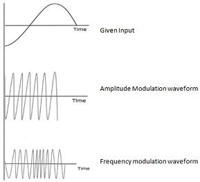
For AM, we can write
c(t) = A sin(2Πfct) [fc = carrier frequency, A = amplitude]
m(t) = M cos(2Πfmt + Φ) = Am cos(2Πfmt + Φ) [fm = input sine wave frequency]
Output equation is
y(t) = Asin(2Πfct) +1/2Am[sin(2Π[fc + fm)t + Φ) + sin(2Π[fc - fm]t - Φ)].
EXPERTSMINDS.COM ACCEPTS INSTANT AND SHORT DEADLINES ORDER FOR ANALOG MODULATION AND FREQUENCY MODULATION ASSIGNMENT – ORDER TODAY FOR EXCELLENCE!
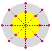
Question 4. Draw the 16 QAM Constellation Diagram having four different amplitude levels and four different phase levels.
4. The following figure represents a 16-QAM Constellation Diagramwith two different levels ofamplitudeand eight different levels of phase can be shown as follows
Question 5. Explain and draw the Error Detection Process for Cyclic Redundancy Check (CRC).
Answer: Let, block of bits as p and bit sequence is taken as m. The output will be (p+m) bits.
CRC is the technique of judgmentmistake in a signal at the receiver end. If a transmitterproduces bit sequence having m numbers for prearranged bits having p block, this is identified as frame check sequence (FCK).
At the receiver end this will be separated by same number and if there is no residue, then it can be granted as no error.
Question 6. Compute the frame check sequence using Cyclic Redundancy Check (CRC) for the following information:
Message = 111010110, Pattern = 101110
Answer:
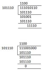
If, Sent data = 111001000
Then Data received has no errors.
But, If, Sent data = 111010110
Then Data received has errors of 11110.
Question 7. Compute the transmitted signal using Direct Sequence Spread Spectrum for the following information:
Input: 101, Locally Generated PN bit stream: 011011010110, T = 4Tc
|
Input
|
101 i.e. +1-1+1
|
|
Bit stream
|
011011010110 i.e. -1+1+1-1+1+1-1+1-1+1+1-1
|
|
Output
|
011011010011
|
Answer: The transmission technology which is used in local areas with wireless transmission are known as DSSS) direct sequence, output.
In this method, if bit pattern and input is given, then output can be formed accordingly.
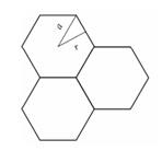
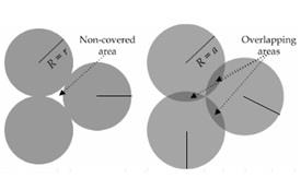
Question 8. Explain why the square and circle shapes cells for cellular communications are not appropriate as compared to hexagonal shape cells.
Answer: According to following figure we can say that, there is no overlapping happen in case of hexagonal shape, and it is considered as main advantage.
GET GUARANTEED SATISFACTION OR MONEY BACK UNDER ANALOG MODULATION AND FREQUENCY MODULATION ASSIGNMENT HELP SERVICES OF EXPERTSMINDS.COM – ORDER TODAY NEW COPY OF THIS ASSIGNMENT!